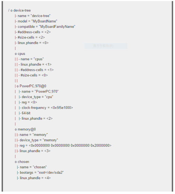
Documentation/devicetree/bindings/gpio/gpio.txt
GPIOs property
Note that gpio-specifier length is controller dependent. In the below example, &gpio1 uses 2 cells to specify a gpio, while &gpio2 only uses one.
gpio1: gpio1 {
gpio-controller
#gpio-cells = <2>;
};
gpio2: gpio2 {
gpio-controller
#gpio-cells = <1>;
};
[...]
chipsel-gpios = <&gpio1 12 0>,
<&gpio1 13 0>,
<0>, /* holes are permitted, means no GPIO 2 */
<&gpio2 2>;
Most controllers are however specifying a generic flag bitfield in the last cell, so for these, use the macros defined in include/dt-bindings/gpio/gpio.h whenever possible
node {
enable-gpios = <&qe_pio_e 18 GPIO_ACTIVE_HIGH>
}
qe_pio_e: gpio-controller.
GPIO_ACTIVE_HIGH: 0 (defined in include/dt-bindings/gpio/gpio.h).
gpio-specifier: "18 0".
gpio-controller
#gpio-cells = <2>;
};
gpio2: gpio2 {
gpio-controller
#gpio-cells = <1>;
};
[...]
chipsel-gpios = <&gpio1 12 0>,
<&gpio1 13 0>,
<0>, /* holes are permitted, means no GPIO 2 */
<&gpio2 2>;
GPIO_ACTIVE_HIGH: 0 (defined in include/dt-bindings/gpio/gpio.h).
gpio-specifier: "18 0".
gpio-controller
Documentation/devicetree/bindings/pinctrl/pinctrl-bindings.txt
pinctrl-#
 pinctrl-names定义了一个state列表。
pinctrl-0是一个sleep state時的句柄(phandle)列表,每个句柄指向一个pin configurationpinctrl-1是一个active state。
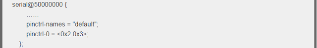 serial device只定义了一个state就是default,对应pinctrl-0属性定义。
pinctrl-0是一个句柄(phandle)列表,每个句柄指向一个pin configuration。
phandle 0x2以及0x3分別是在別處定義的pin configuration。
pinctrl-names定义了一个state列表。pinctrl-0是一个sleep state時的句柄(phandle)列表,每个句柄指向一个pin configurationpinctrl-1是一个active state。
serial device只定义了一个state就是default,对应pinctrl-0属性定义。pinctrl-0是一个句柄(phandle)列表,每个句柄指向一个pin configuration。
phandle 0x2以及0x3分別是在別處定義的pin configuration。
Documentation/devicetree/bindings/interrupt-controller/interrupts.txt
property:
-
interrupt-parent: is used to specify the controller to which interrupts are routed and contains a single phandle
-
interrupts:
#interrupt-cells:1
defines the index of the interrupt within the controller
#interrupt-cells:2
the first cell defines the index of the interrupt within the controller
the second cell is used to specify any of the following flags:
bits[3:0] trigger type and level flags
1 = low-to-high edge triggered
2 = high-to-low edge triggered
4 = active high level-sensitive
8 = active low level-sensitive
interrupt-parent: is used to specify the controller to which interrupts are routed and contains a single phandle
interrupts:
#interrupt-cells:1
defines the index of the interrupt within the controller
#interrupt-cells:2
the first cell defines the index of the interrupt within the controller
the second cell is used to specify any of the following flags:
bits[3:0] trigger type and level flags
1 = low-to-high edge triggered
2 = high-to-low edge triggered
4 = active high level-sensitive
8 = active low level-sensitive